RUDDER GUST LOCK:
Even though I use the control lock inside the airplane when it is parked, I wanted a more secure control lock for the rudder during overnight stays. From experience of other RV10 owners, the rudder can loosen the rudder stop when the rudder flaps back & forth in the wind when parked..
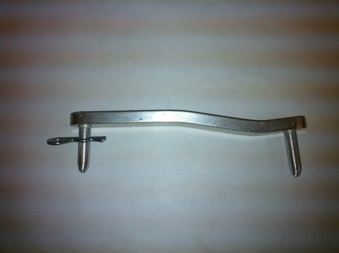
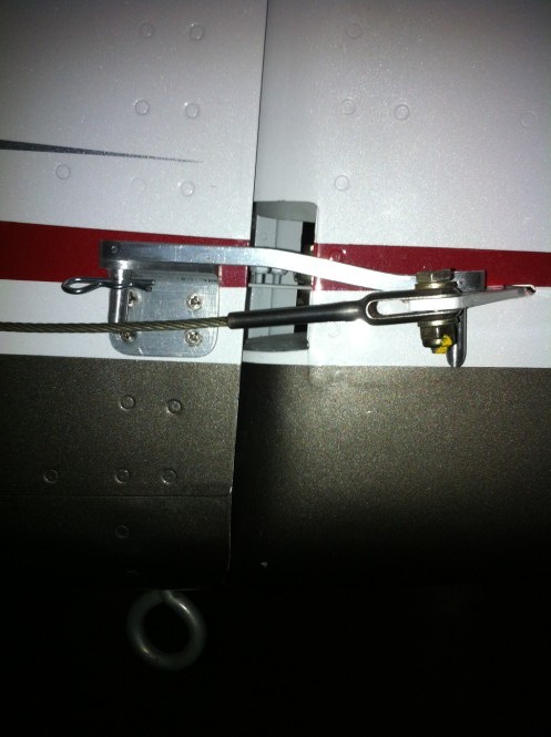
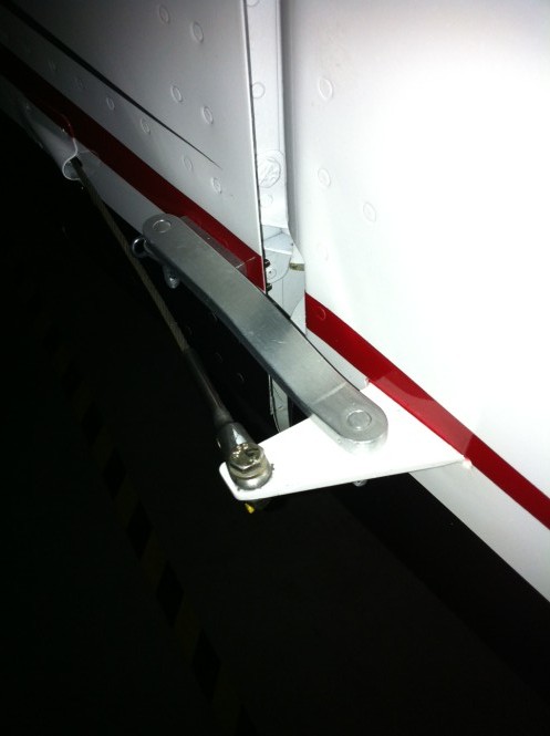
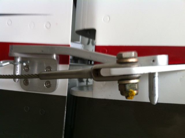
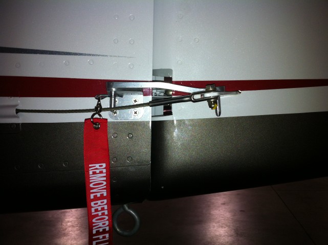
This control lock has a bracket added to the exterior of the airplane at the back of the empennage. A solid 5/8" x 1/4" rectangular bar was built with a 1/4" rod installed through each end. A 1/4" hole was drilled in the center of the rudder control horn to accept one end of the bar's 1/4" rod. A 1/4" hinge pin was used to secure the rudder lock to the aircraft.
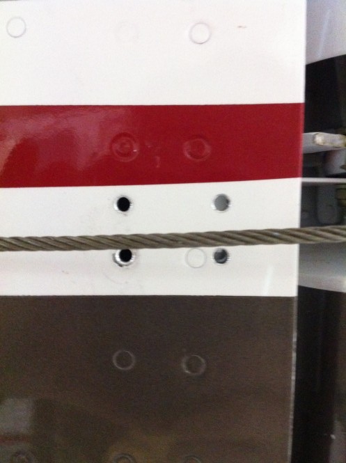
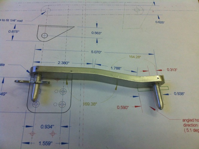
The drawings below show the construction of the rudder lock parts. The forward attach bracket, uses one of the existing rivet holes attaching the skin to the F-1011 rib. The two aft holes attach the bracket to the empennage and the F-1012 Rib. A spacer is required between the skin and the F-1012 rib for the two aft holes.
The 1/4" pins are parallel to each other. To do this the aft pin's hole needs to have a 5 degree tilt towards the front. This parallel alignment allows easy install of the rudder lock. A 1/16" hole was drilled in the forward pin to allow attachment of the the hinge pin. A "Remove Before Flight" ribbon was attached to the hinge pin clip.
Even though I use the control lock inside the airplane when it is parked, I wanted a more secure control lock for the rudder during overnight stays. From experience of other RV10 owners, the rudder can loosen the rudder stop when the rudder flaps back & forth in the wind when parked..
This control lock has a bracket added to the exterior of the airplane at the back of the empennage. A solid 5/8" x 1/4" rectangular bar was built with a 1/4" rod installed through each end. A 1/4" hole was drilled in the center of the rudder control horn to accept one end of the bar's 1/4" rod. A 1/4" hinge pin was used to secure the rudder lock to the aircraft.
The drawings below show the construction of the rudder lock parts. The forward attach bracket, uses one of the existing rivet holes attaching the skin to the F-1011 rib. The two aft holes attach the bracket to the empennage and the F-1012 Rib. A spacer is required between the skin and the F-1012 rib for the two aft holes.
The 1/4" pins are parallel to each other. To do this the aft pin's hole needs to have a 5 degree tilt towards the front. This parallel alignment allows easy install of the rudder lock. A 1/16" hole was drilled in the forward pin to allow attachment of the the hinge pin. A "Remove Before Flight" ribbon was attached to the hinge pin clip.
|
|


|
|
|
|
|
|
||||||||||||
|
|
|
|
|


AILERON & ELEVATOR GUST LOCK:
There were a couple of people that had come up with control gust locks for the RV10, but none would work with my interior.
I noticed a gust lock that Robin(at)PaintTheWeb.com had made. It was simple and would hold the controls in a neutral position. I decided to build my own gust locks using Robin's pictures and ideas as a guide. I purchased the Quick Release Pins from Reid Supply. The pins are 1/4" diameter and 1/2" grip.
I taped the elevator and aileron controls in their neutral position. This allowed me to place the gust lock in the correct position. Using some scrap 3/16" aluminum plate, I cut out the base for the gust lock. 2 - 3/4" aluminum angle with a 1/8" bar, spacing them apart, was used for the receptacle for the tang that was attached to the control stick. As Robin had stated I found that the position of the tang on the stick was a non issue for clearance. I had another piece of scrap aluminum sheet that was .08" thick. It was used for the mounting plate that attached to the seat. This plate was attached to the seat structure using the existing #8 screws. Under the front 3/4" of this plate, I attached 3/16" receptacle for the pins to attach to. The stick "tang" was made from to electrical pipe attachment clamps. I trimmed the clamp to allow 2 - 1/8" pop rivets to attach each clamp. The pipe clamps already had a 1/4" hole for the tab, so I bolted these together. Then I placed the assembly over a 3/4" steel water pipe and bent them to the diameter of the stick.
|
|
|
|
|
|||||
|
|
|
|
|


