I did not like the way the rudder cables came out of the tunnel up to the pedals. I kept the cables inside the tunnel and connected the cable to the rudder pedals inside the tunnel. The cable length was not modified from the plans.
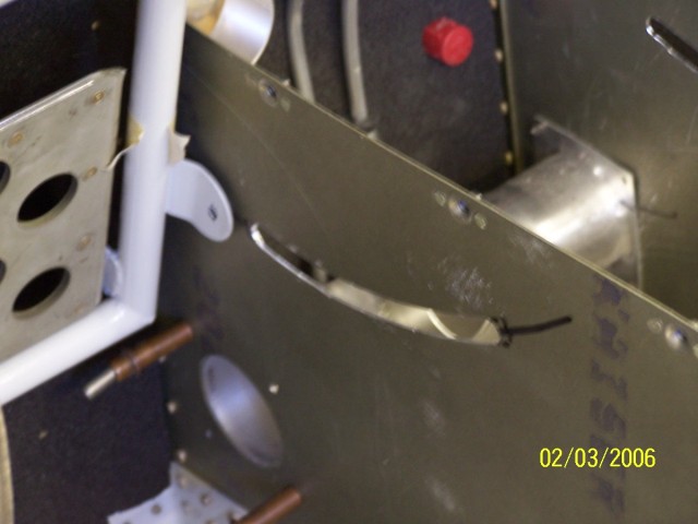
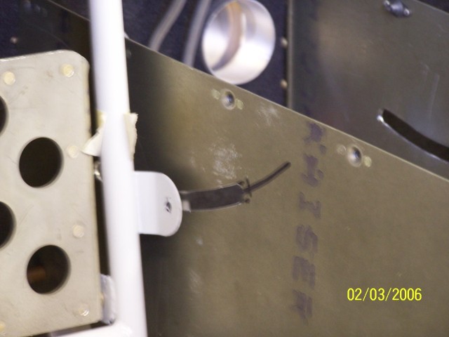
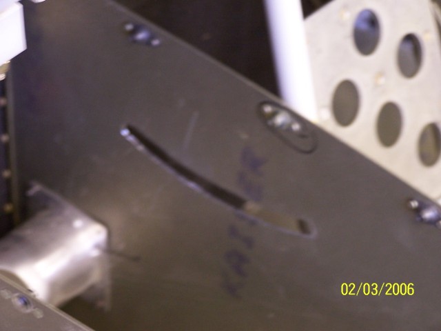
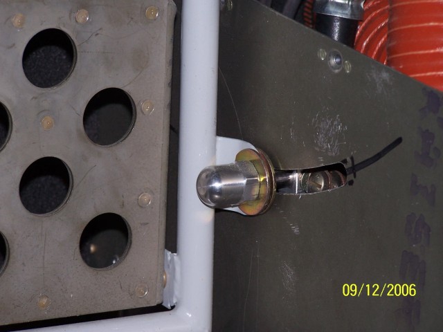
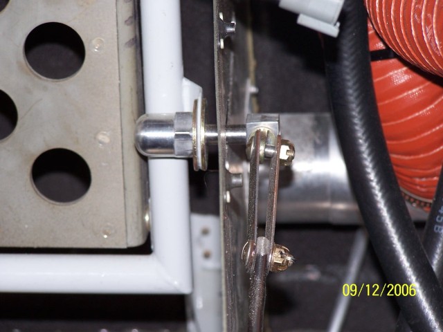
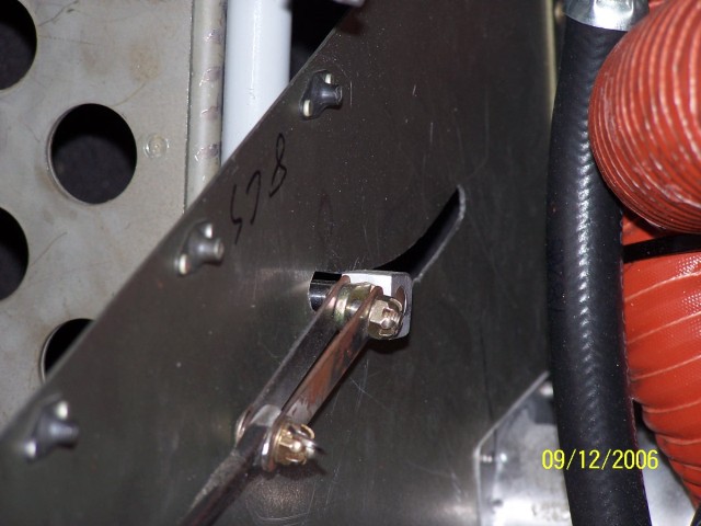
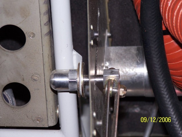
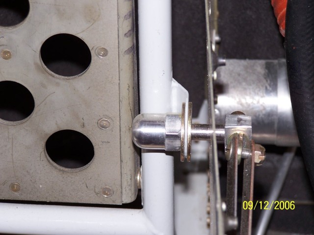
A "smiley" face cutout was made on the tunnel's side. A marker was placed in the existing rudder pedal cable attachment hole. The pedal was swung back and forth to mark the tunnel side. The slot was cutout with a router.
A special attachment bolt was made to fit in the cable attachment hole. The bolt head was made to contact the rudder pedal vertical tube to prevent the tab from bending. A fitting was placed on the inside end of the bolt and the rudder cable was attached to it.
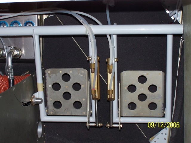
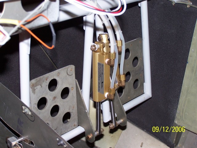
The rudder pedal actuators were reversed in their mountings so the majority of the hose/tubing were above the pedals and out of site. The original routing of the hose/tubing is the same as the plans.
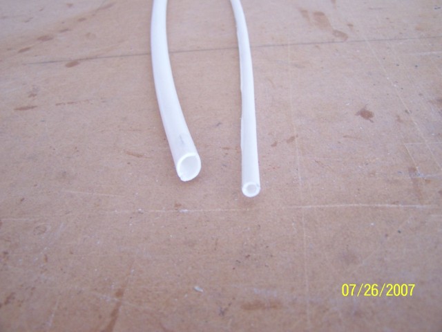
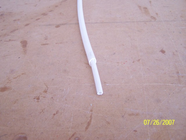
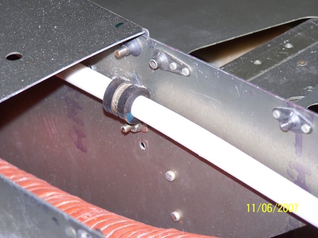
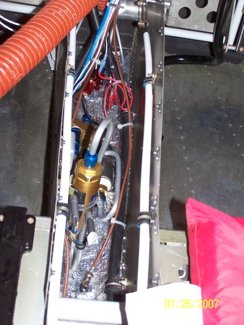
I found cable covers at the local West Marine dealer. One cover has an 1/8"ID and goes over the rudder cable. The other cover is 5/16"ID and fits over the rudder cable cover. This allows the rudder cable to move inside. The outer cover was clamped to the side of the tunnel. These covers are split down the middle to allow installation on an existing cable. The covers kept the cable from slicing through any hoses (fuel and a/c hoses), tubing and wiring. The covers continued through the tunnel and terminated aft of the aft wing spar.
Click images for larger view
