click images for larger picture
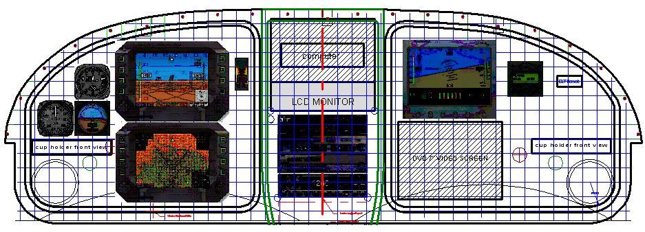
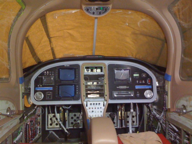
The panel will include:
Dual Cheltons
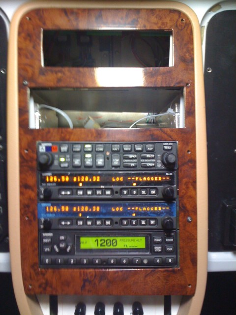
Dual Garmin SL30 Nav/Com
Transponder
Audio Panel
Standby Instrumentation
AFS Engine Monitor and AOA
Two Cup Holders
Custom Fresh Air vents routed through panel
On board computer
7" Touchscreen flip up monitor
Dual Cheltons
Dual Garmin SL30 Nav/Com
Transponder
Audio Panel
Standby Instrumentation
AFS Engine Monitor and AOA
Two Cup Holders
Custom Fresh Air vents routed through panel
On board computer
7" Touchscreen flip up monitor
To go along with the custom interior installed in the RV10, I decided to build a custom instrument panel.
After making a cardboard mockup of the panel to verify my dimensions, I used the panel drawing to come up with the dimensions I needed to build the panel out of 1/2" MDF board.
I printed a full scale drawing using my computer's printer. I set the paper size to 8.5 x 14. It took eight sheets of paper to print the full scale drawing. Then I had to cut and paste the sheets together to get the full drawing. The full drawing was then glued to the MDF board.
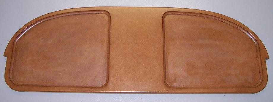
After cutting along the outside lines of the pattern, I had the main wood model to use to make the other MDF parts required.
After trying different placements of the Cheltons, I decided to mount the Cheltons vertical. This would allow for a molded center console to flow up into the middle of the instrument panel.
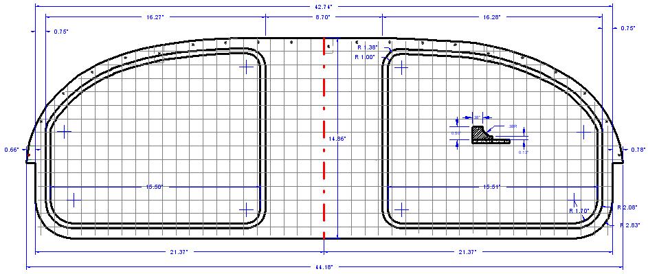
Using Quick Cad, I drew the panel on my computer. The panel outside dimensions are different from the stock panel supplied by Vans. This was to allow for the custom glare shield that fits over the top of the panel. The panel is also about an inch lower than the stock panel to allow for the vertical alignment of the Cheltons.
Using Quick Cad, I drew the panel on my computer. The panel outside dimensions are different from the stock panel supplied by Vans. This was to allow for the custom glare shield that fits over the top of the panel. The panel is also about an inch lower than the stock panel to allow for the vertical alignment of the Cheltons.
I used a 3/8" cove router bit to make the decorative cut in the 1/2 MDF board. Setting the bit at the top of the MDF board allowed for a small inset for the metal panel to sit in.
The backing plate was screwed to the back of the pattern and then several coats of wax was applied for a mold release.
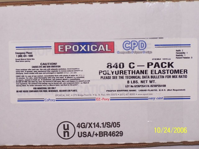
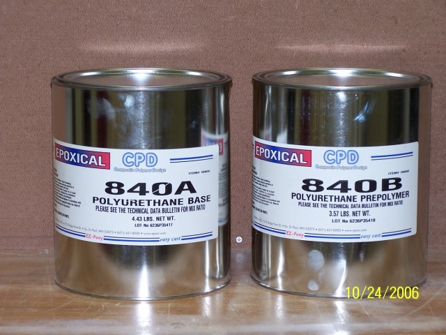
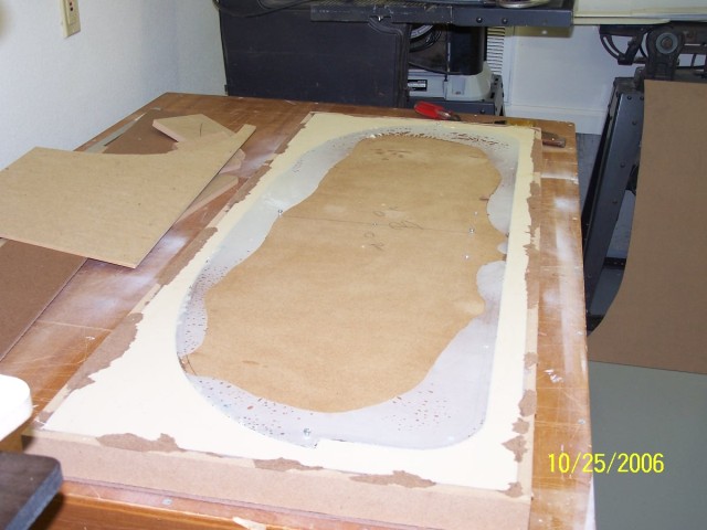
After some research I found a rubberize system that would allow me to make a reverse mold of the pattern. This would then allow me to glass inside the mold to make an identical part of the wood pattern. A bonus using this system was the rubberized mold would make it easier to remove the fiberglassed part. Epoxical will duplicate the smallest details in the pattern. The product's name is Epoxical 840 C and sold by Advanced Plastics in Tulsa. The Epoxical is a two part mixture. Two gallon cans are supplied in the kit. The A & B cans are half filled. Mixing the two cans together is required to activate. It took four gallon kits to fill my mold box 46" x 18" x 1.5".
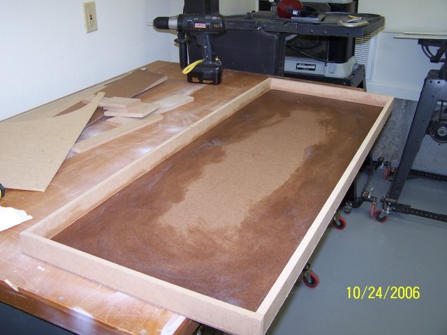
I built a wood box to place the panel pattern in. Wax was applied to the bottom of the to allow for pattern removal. To keep the rubber mold in the box, I did not wax the sides of the box.
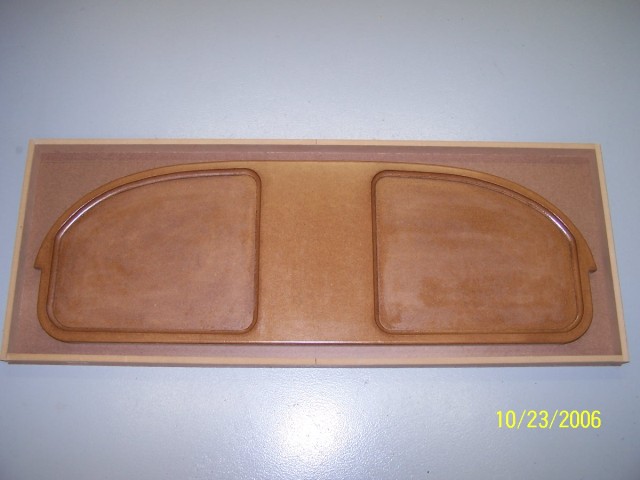
The panel pattern was place in the center of the wood box.
The panel pattern was place in the center of the wood box.
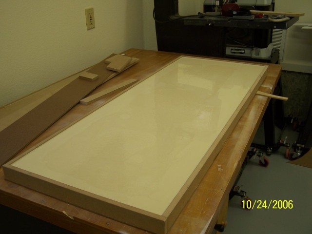
Not sure if I calculated correctly, I mixed one gallon kit at a time and then poured it over the mold. It took the exact 4 gallons to fill the wood box. I allowed for 1/2" depth above the pattern.
After about 4 hours the poured mixture had turned to a hard rubber. I waited 24 hours before removing the pattern from the mold.
After about 4 hours the poured mixture had turned to a hard rubber. I waited 24 hours before removing the pattern from the mold.
Each Epoxical gallon kit weighs 8 pounds. The mold ended up weighing 40 pounds including the wood pattern and box. I flipped the box over to remove the bottom. This would allow removal of the wood pattern. It would be best to apply a small bead of silicon seal around the box where it meets the bottom before pouring the Epoxical. Epoxical did seep slightly and bonded the sides to the bottom. A small chisel and the bottom was removed exposing the wood pattern.
Backing out a few of the screws, used to attach the wood back to the pattern, gave me something to grip with pliers to pull the wood pattern from the mold.
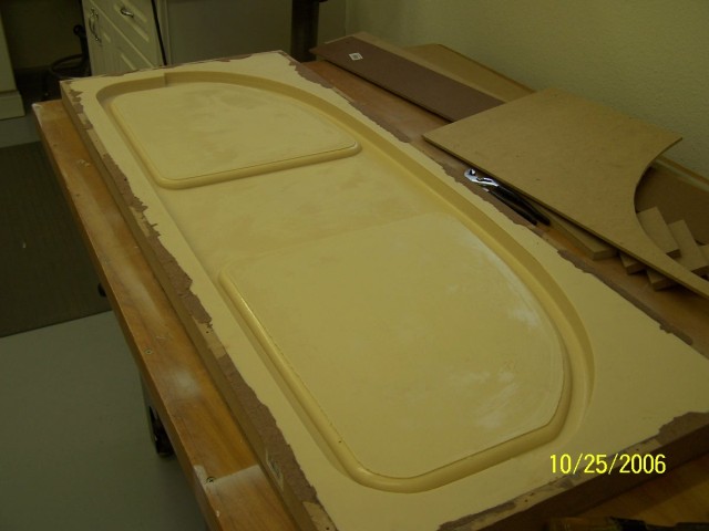
The rubberized mold made a perfect copy of the the wood pattern.
Backing out a few of the screws, used to attach the wood back to the pattern, gave me something to grip with pliers to pull the wood pattern from the mold.
The rubberized mold made a perfect copy of the the wood pattern.
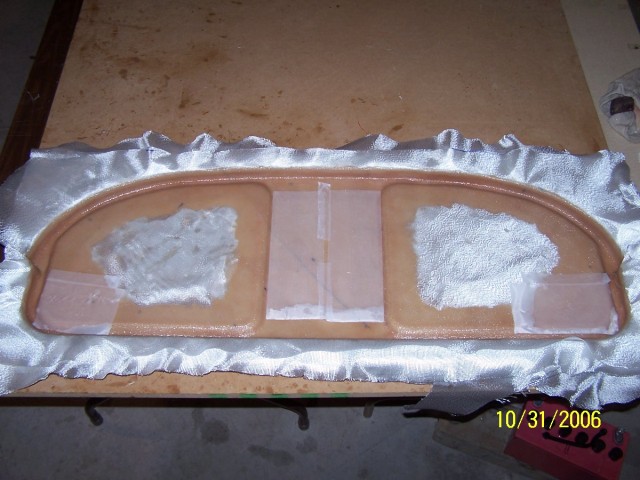
I decided I would use 7 layers of 5oz fiberglass cloth. Between two of the layers I would include a 1" strip of glass matt around the perimeter of the panel for added stiffness. I cut 6 pieces of cloth 20" x 50" with the weave running at 45 degrees. I found that it is easier to get the cloth to lay down in compound curves and corners with cloth cut at 45 degrees. The first layer of cloth consisted of 5" x 6" strips around the perimeter depressions. Before I placed the strips in the mold, I mixed a batch of slurry (epoxy with micro balloons) and poured this over the depressions in the mold. This would help to fill any place the cloth did not go completely into the mold. Using the West System epoxy system, it took me 2 1/2 patient hours to apply all seven layers into the mold.
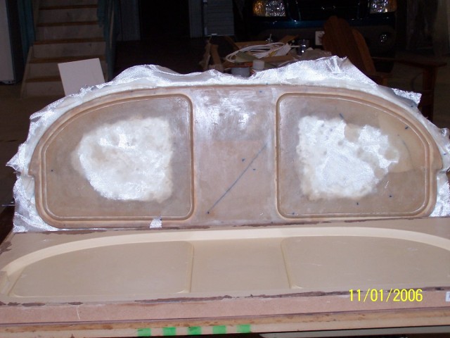
After 24 hours, I pulled the panel part from the mold. Using a couple coats of mold wax, allowed the part to easily pull free. Using my small air powered reciprocating saw, I trimmed the excess cloth from the mold.
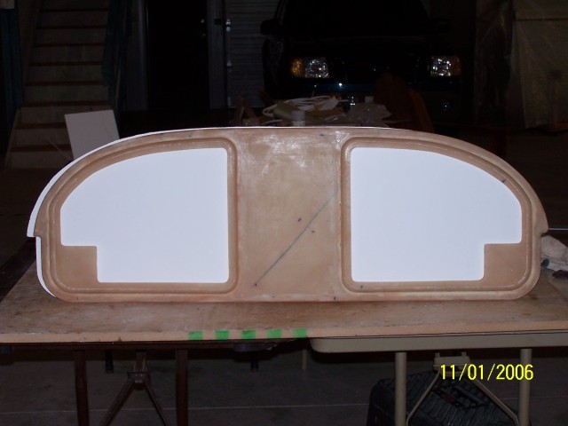
I used 1/2" masking tape to mark the inside cut of the mold. This allowed for a ledge for the metal panel inserts to lay on. The lower corner squares will be use to attach the lower edge of the panel to custom ducts attached to the fresh air vents. This would provide lower anchor points for the panel and easy attachment of the custom air vents in the panel.
I used 1/2" masking tape to mark the inside cut of the mold. This allowed for a ledge for the metal panel inserts to lay on. The lower corner squares will be use to attach the lower edge of the panel to custom ducts attached to the fresh air vents. This would provide lower anchor points for the panel and easy attachment of the custom air vents in the panel.
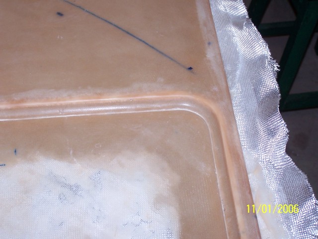
This picture shows the detail achieved using the rubber mold concept. I am very pleased with the panel's detail. A few imperfections were found when the panel was pulled, but they can be corrected with epoxy fill.
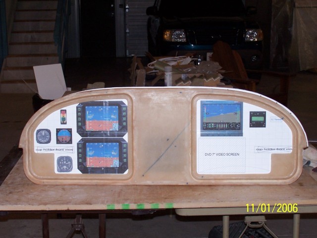
This shows the final trim of the panel. The panel's depth is 5/8" thick. The preliminary instrumentation layout was placed behind the panel to show the instrument locations. The AOA gauge will be mounted to the right of the top Chelton display. Threaded Clickbond studs will be bonded to the back of the panel for attachment to the panel frame.
You have probably wondered about the switch locations. They will be placed in a hidden panel on the center console. The fuse panels located on the left kick panel.
You have probably wondered about the switch locations. They will be placed in a hidden panel on the center console. The fuse panels located on the left kick panel.

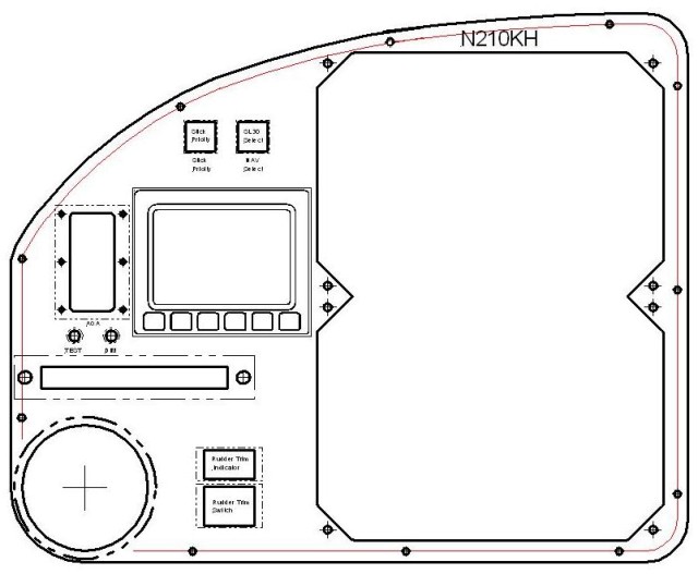
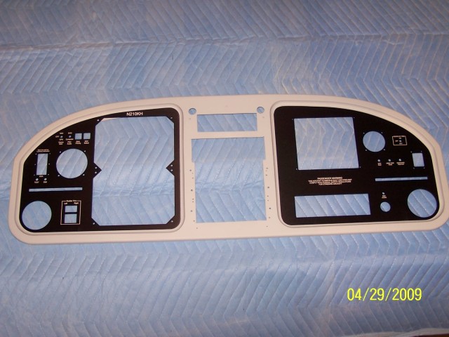
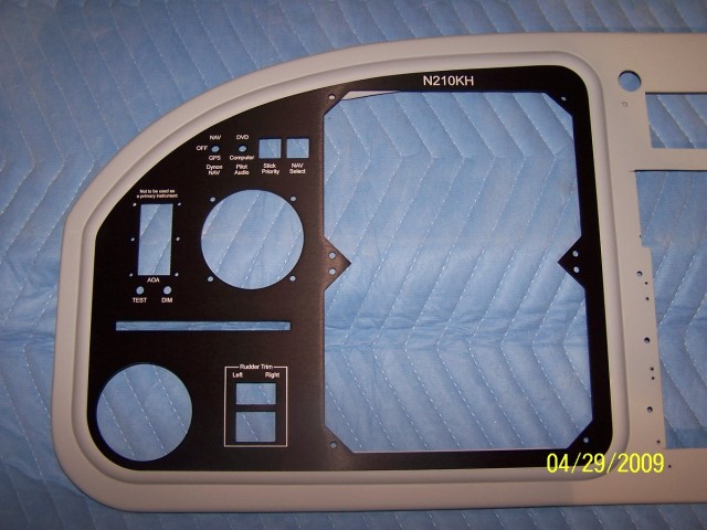
The final decision for the instrument panel layouts. The left panel will have dual Cheltons, Advanced Flight Systems AOA gauge, rudder trim, cup holder and the small Dynon EFIS for the backup instrument.
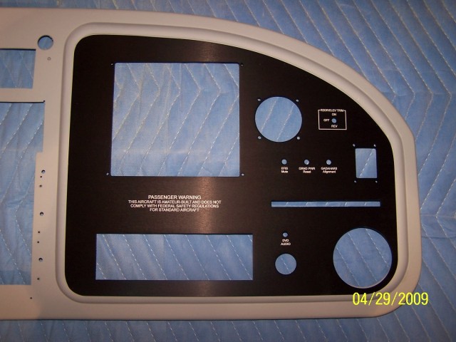
The right panel will have Advanced Flight Systems engine monitor (coupled to the Cheltons), TruTrak autopilot, ELT switch, cup holder, DVD/XM/RADIO/IPOD flip up touch screen and accessory power plug.
The right panel will have Advanced Flight Systems engine monitor (coupled to the Cheltons), TruTrak autopilot, ELT switch, cup holder, DVD/XM/RADIO/IPOD flip up touch screen and accessory power plug.
The panels were made locally by Ideal Specialty in Tulsa. I provided the cad drawing and cut the panels out of 1/8" aluminum. The panels were black anodized and then the lettering was laser etched into the panels. This process was a little cheaper than my RV8 which had the lettering engraved into the panels.
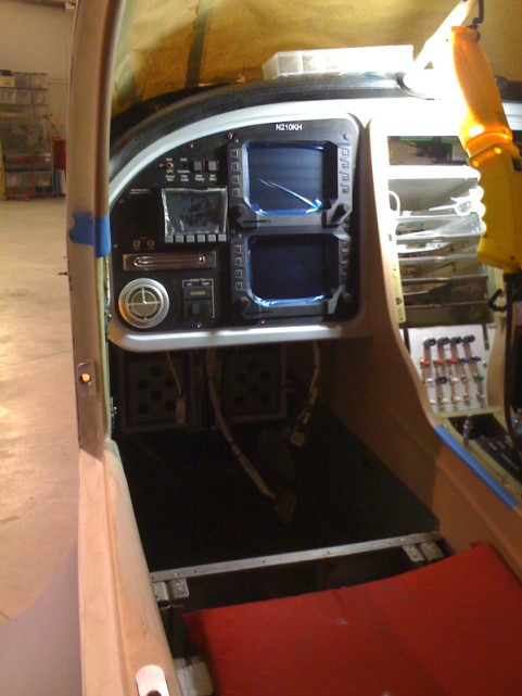
Install of completed instrument panel and the Cheltons and radios wired and operating
