To go along with the instrument panel installed in the RV10, I decided to build a custom center console. The pictures on this page show the construction of the console. This link shows the completed console.
The console will include:
Console mounted engine quadrant
Electrical switches in hidden panel
Avionics
On Board Computer
Flip up touchscreen monitor
Arm rest storage compartment
An overhead environmental switch panel
I used my Auto Cad program to design the center console. After measuring, building cardboard mockup, measuring, building cardboard mockup I finally was satisfied with the dimension I needed. I wanted to build the console outside of the airplane on my work table. I needed to build an exact replica of the center tunnel and instrument panel locations. I wanted the radio rack to slant aft and flow into the center console. The new console should be able to fit over the existing tunnel cover supplied in the kit. The console used ideas from the Cirrus aircraft. A custom throttle quadrant would be purchased from DJM Mfg. The throttle quadrant would be the CT83F quadrant, the quadrant used in my RV8, and incorporating the "T" style throttle knob and shorter prop and mixture handles available on the CMCT3L quadrant.
I made the wood jig out of MDF board. I printed a full scale layout of the computer drawing and glued it to the MDF board. I allowed for the 5/8" depth of the custom instrument panel.
Click images for larger view
To build the console, I used 1/4" PVC foam from Aircraft Spruce. Using ideas from the Varieze I built in 1978, the foam would be the jig and the part. Using temporary clamps, I placed the foam on the wood jig. To make the foam follow the curve sides, I pushed
T-pins through the outside of the foam, bent a hook on the T-pin end and attached safety wire from the pin to a screw.
3 layers of 5oz bi-directional glass were applied to the foam's outside. The glass was cut on the bias - meaning the weave ran at a 45 degree angle. After the layup had cured, I attached wood brackets on the console side with bondo. This would allow the part to be pulled from the jig and turned upside down. Without the wood brackets, the part would be flimsy and the original shape would not be correct.
The console should fit over the existing tunnel cover supplied with the kit. To do this and minimize the width of the console, I removed the foam down to the fiberglass. This would close off the bottom of the foam edge and also provide a firm attaching edge. Two layers of 5oz glass was applied over the exposed foam and the attaching edge. This would make a sandwiched the foam between the two glass sides.
The original wood buck for the side layups is trimmed during the various stages of assembly. Checking fit of console sides to panel mockup
Wood blocks were used to hold the console width to the panel. Flanges were glassed onto the console radio rack area. After the flanges had cured, holes were drilled and clecos were used to position the console radio rack on the instrument panel.
To make the cover (insert) for the radio rack and the center part of the console, I made a wood buck of the shape of the insert. I found some old laminate material and glued the laminate to the wood buck. 7 layers of 5oz glass and one layer of mat were applied in the middle of the layup to achieve a thickness of 1/8".
After the layup of the console insert had cured, the part was removed from the mold and fit and trimmed to the console. The laminate material used on the mold allowed for a smooth surface on the insert cover. The insert will be covered with a wood veneer when the console is completed.
These pictures show the finished top edge of the console. The corners were made to match the radius corners of the panel.
It was decided to continue the console insert up the front of the storage compartment. The fuel valve will be located in the area of the cleco fastener.
A flange was added to the front of the console to support the insert panel. This flange will be eventually trimmed back to allow for the switch compartment door and the avionics installation.
The original size of the glove box was determined to be small, so I added 3" to the height of the box.
To finish and seal the exposed edges of the foam lay-up, 1/4" of foam is removed with a dremel tool. A mixture of epoxy resin and cotton fill (flox) is applied over the foam to the top of the fiberglass sides. This strengthens the foam edge.
"Big Al" trying out the console. Picture 1 shows console to leg clearance. The shape of the console was determined by leg and stick movement. Picture 2 shows the avionics location. Picture 3 shows the switches that will behind a pivoting panel door. The throttle location will be located in the area of Al's hand. Note the custom glareshield over the panel.
The main switch panel is hidden behind a pivoting door. The door was cut from the console insert panel.
I used T-nuts for mounting the hinge pivots. The T-nuts were installed back words with a flox mixture into the console side. A threaded rod was inserted through the console to align the T-nuts during assembly.
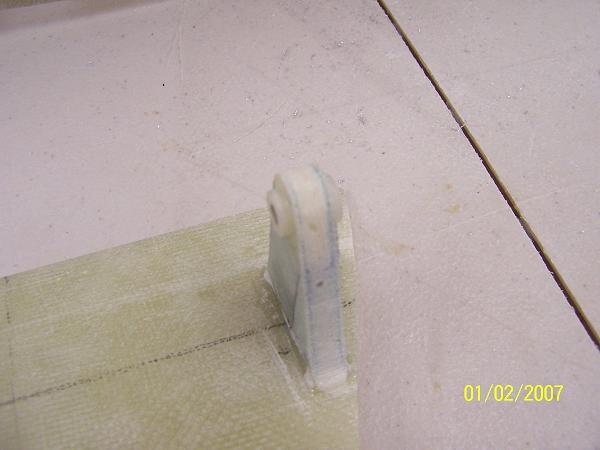
I made the door pivots from scrap foam/fiberglass sandwich lay-ups.
A hole was drilled through the door pivots and a nylon bushing was placed in each hole. Flox was used around the exposed foam and to anchor the bushing.
Using the same threaded rod for alignment, the pivots were attached to the door with flox.
I used knurled allen screws to attach the door to the console. A small hole was drilled into each screw for safety wire attachment.
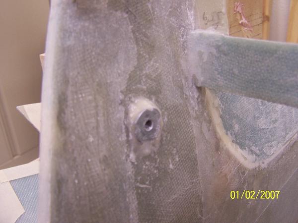 |
"T" nut floxed to console side |
|
 |
pivots attached to door |
|
|
 |
door hinged to console |
|
 |
door clearance and operation |
|
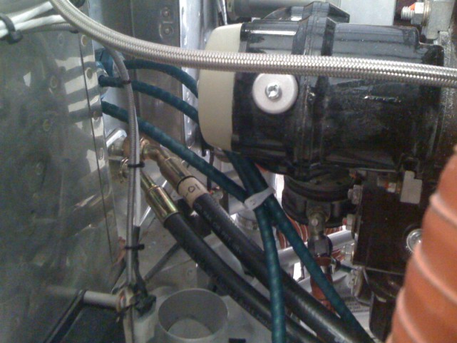
The Andair fuel valve will be inset into the console top. A 3" hole was drilled through the console insert and the top of the console. The fuel valve was mounted to a plate. The plate was attached to the top of the console from the bottom. The console insert will lay over the top and hide the attachment screws.
The new fuel valve with extension and tube routing is available at this link Fuel Valve.
 |
console trimmed for quadrant and fuel valve |
|
 |
alumnium angle attached to quadrant |
|
 |
quadrant mounted to console |
|
 |
console insert overlay with door closed |
|
 |
console insert with door open |
|
 |
cable routing to quadrant |
|
|
|
A custom throttle quadrant CT83F was purchased from DJM Mfg. The quadrant was modified with a "T" handle for the throttle and shorter prop and mixture levers. A pattern was made of the top of the quadrant and transferred to the top of the console for trimming. To be able to mount the quadrant to the bottom of the console top, aluminum angles were attached to both sides of the quadrant. Custom length cables were ordered from Vans and installed on top of the tunnel. The console installs over the tunnel top and hides the cables.
The armrest for the console was made out of 2" thick polyurethane foam. The base of the armrest is a 1/4" PVC foam layup. I used the armrest base as a pattern to cut the 2" foam. The foam was bonded to the base and then 2 layers of glass cloth were applied to foam. An aluminum base cover was added after the armrest was completed. Inverted T-nuts were installed in the foam lay-up for attachment of the aluminum base cover and hinge attachment.
The armrest was made undersized to allow for a padded leather covering. A bracket was installed in the glove box to house the Hobbs Meter. I purchased a set of cabinet hinges ( Liberty H01068 Hinge ) from Home Depot. These hinges are spring loaded and will be hidden when the armrest is closed. T-nuts were used to attach the hinges to the armrest base and the console. Inverted "T" nuts were bonded into position with a flox mixture.
 |
foam attached to sandwich lay-up |
|
 |
armrest shaped and glassed |
|
 |
armrest in closed position |
|
 |
armrest in open position |
|
 |
hinge attachment |
|
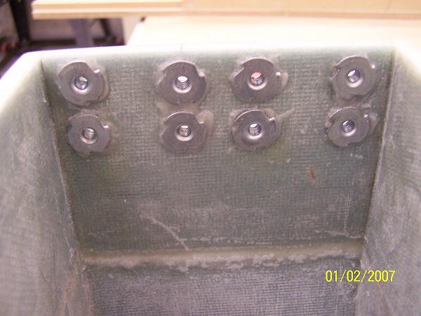 |
"inverted" T-nut attachment with flox. |
|
The door on the console is held open by a magnetic latch. When the door is opened, a LED strip light under the door will come on to illuminate the switches.